Barrel weld seam thinning trimming machine (1)
Barrel weld seam thinning trimming machine (1)
3602 Factory Tan Xinhua
First, the question is raised
As we all know, the leakage of steel drum is mainly in the triangle area of ​​the T-shaped mouth. The reason is that the lamination of the weld seam is not good. The specific analysis is as follows:
The 20QL steel barrel body plate is 1.25mm thick. After shearing and grinding, the thickness of the short side edge is generally about 1mm, as shown in Figure 1.
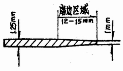
Fig.1 Variation of thickness of steel plate edging
After welding by automatic welding machine, the cross-sectional shape of the weld is shown in Fig. 2. The shape of the bead formed after assembly is shown in Fig. 3.

Figure 2 Automatic welder weld cross-section shape

Figure 3 Curling shape after automatic weld assembly
After the manual semi-automatic welding machine is welded, the cross-sectional shape of the weld is shown in Fig. 4, and the crimped cross section formed after assembly is shown in Fig. 5.

Figure 4 Semi-automatic weld cross-sectional shape
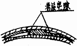
Figure 5 Semi-automatic weld seaming section
Analysis of the characteristics of automatic welding machine and manual semi-automatic welding machine welding, it can be known that: in the automatic welding machine welding process, the weld seam edge is narrow, generally only 3 ~ 5mm, and the welding wheel is wider (about 20-30mm). Therefore, during the welding process, the weld bead is in the full containment of the welding wheel (see Figure 6). Under the action of the pressure and current of the upper and lower welding wheels, the entire lap is completely melted to form the shape of the weld shown in Fig. 2. The maximum thickness is generally between 1.3-1.6mm, although it is larger than the barrel thickness of 1.25mm, it is similar. Therefore, the gap of the coil layer in the weld bead triangle of the automatic welder is small, and the possibility of leakage is small. Because the manual semi-automatic welding machine welding wheel is narrow (6 ~ 8mm), the welding edge value is better. Wide (12-15mm), so in the welding, under the action of the welding wheel pressure and current, the situation of Figure 7 will appear. The thickness of the weld section is about 2--, 2.5 mm. A horn-like warp occurs when the edge of the lap is outside the restraint of the welding wheel. As a result of the warpage, the L3 size in Fig. 7 exceeded 2.5 mm. This size is much larger than the thickness of the barrel. After assembly, the voids at the curling edge are large, thus increasing the likelihood of leakage.

Figure 6 Fully-welded welding wheel full-enhanced edge

Fig. 7 Warping of the edging outside the semi-automatic welding machine
It can be seen from the analysis that in order to reduce the leakage rate of the steel drum, that is, to reduce the leakage rate at the wrap of the triangular zone, it is necessary to try to minimize the void of the coil at the beading triangle. In order to reduce the thickness of the wound layer, the thickness of the steel plate at the weld must be as close as possible to the thickness of the barrel. Therefore, the barrel end seam pressing and trimming machine with this function came into being.
Second, the characteristics and structure of the weld seam thinning machine
1. Characteristics
As described above, the weld bead trimming machine is used to press both ends of the barrel weld and cut off the iron tongue at both ends of the weld. To ensure the leakage of the triangle in the T-shaped mouth of the steel drum is guaranteed.
At present, the more mature weld seam trimming machine is produced by RMG of Germany. It uses a more advanced programmable controller (PC) and a non-contact inductive switch to form a control system. Mechanical, hydraulic, pneumatic, electrical appliances are reasonably arranged, the structure is reasonable, the operation is stable, the noise is small, and the operation is simple.
2. Weld seam thinning machine structure
(1) The structure of the structural weld thinning trimming machine is shown in Fig. 8.

Figure 8 Schematic diagram of weld seam thinning trimming machine
1-squeeze wheel (1 on the left and right); 2-cutting knife (1 on the left and right); 3-cutting cylinder (1 on the left and right); 4-extruding cylinder (1 on the left and right); 5-pressure ring (left and right) Each 1); 6-left standing bracket; 7-column (four in total, two in each of the upper and lower); 8-active standing bracket; 9-guide sleeve; 19-adjusting handle; 11-adjusting screw; Lock nut; 13-right stand; 14-press tank; 15-hydraulic station; 16-drum cylinder (1 for left and right); 17-base
In the figure, the function of the pressing ring (key 5) is to position the bucket frame; the pressing wheel (key 1) presses the weld seam, the required pressure is supplied by the squeeze cylinder (piece 3), and the trimming knife (piece 2) is cut. To remove the iron tongue squeezed at both ends of the weld, the required cutting force is fixed to the left vertical bracket (key 6) and the right vertical frame (piece 13) by the trimming cylinder (key 3). The movable stand (piece 8) is slidable along the guide post through the guide sleeve (key 9), and the force required to advance and retreat is supplied by the pressure cylinder (piece 14); the adjustment handle (piece IO) adjusts between the pressure rings Static distance. After adjusting the distance, it is locked by the lock nut (key 12); the function of the barrel removal cylinder (piece 16) is to remove the barrel from the press ring after the completion of the thinning and trimming action and the movable stand is retracted; hydraulic station (item 15) Provide suitable oil pressure for each cylinder. The left and right vertical brackets and hydraulic station are fixed on the base (piece 17).

Figure 9 Schematic diagram of the operating position of the trimming machine
1-Main motor running indicator (HL3); 2-main motor start button (SB4); 3-control power indicator (HL2); 4-control power start button (SB2); 5--stop button (SBl); 6-Power indication (HLl); 7-heat indicator (HL4); 8--jog, step, automatic selection switch (SAI); 9-over temperature indicator (Hl5); 10-main motor stop button (SB3 11-total power switch (QSl); 12-manual work select dial (SA2); 13-dial plate nameplate; 14-station button (SB5); 15-station button (SB6).
(2) Local operating procedures:

(3) Operating procedure description:
1 Schematic diagram of the feeding mechanism is shown in Figure 10.

Figure 10 trimming machine feeding mechanism
The piece 1 is fixed to the piece 2 by bolts. If the relative position of the piece 2 and the piece 1 is not suitable, the workpiece 3 may be fed inaccurately, and the barrel action may crush the barrel frame. The position between the piece 1 and the piece 2 can be adjusted by bolts. The feed rack is driven by a long stroke double acting cylinder. After the barrel frame is transferred from the upper process, the weld seam should be manually found, so that the weld seam is in the vertical upward position, which creates conditions for the thinning and trimming of the lower process.
2 pressure barrel
The pressure barrel is pressed against the barrel by the pressure cylinder cylinder. When jog operation, turn the dial SA2 to No. 4, and then press any one of SB5 or SB6 to realize the pressure cylinder forward pressure bucket; dial the dial to No. 5, press SB5 or S, B6 , the pressure tank cylinder is reset.
8 extrusion
The weld is pressed thin by the squeeze wheel. The squeeze wheel is driven by a squeeze cylinder. When jogging, dial the dial to No. 6, and then press any of the SB5 or SB6 buttons to advance the squeeze cylinder for extrusion. Dial the dial to No. 7, press SBs or SB6, and the squeeze cylinder will be reset.
4 trimming
The trimming is to remove the excess metal after extrusion. When jogging, dial the dial to No. 8, and press one of the SB5 or SB6 buttons to advance the trimming cylinder. Turn the dial to No. 9, and press one of the SB5 or SB6 buttons to return the trimming cylinder to its original position.
5 off barrel
The barrel removal is to prevent the barrel from getting stuck on the pressure ring, and the cylinder is used to push the barrel away from the pressure ring. When jogging, dial the dial to No. 9. Press SB5 or SB6 to release the barrel, release SBs or SB6, and remove the barrel.
(4) Operational requirements and safety
1 When operating, pay attention to the values ​​of the indicator table of the power supply, air source and hydraulic system. The gas source and hydraulic system pressure must be adjusted to the appropriate values. The gas supply system must be equipped with a safety valve and a gas water separator. The maximum air pressure is adjusted at O. 7MPa to ensure safety. The working pressure of the hydraulic system must not exceed 10 MPa.
2 All are in the reset position before manual operation or automatic operation. When jogging, each action is required to reset this action in order to operate other actions, or to operate according to the operating procedure, to avoid damage to the components by mutual impact.
8 The starting position and working stroke of each cylinder are controlled by the travel switch (ie, the sensor switch), so the position of the sensor switch should be appropriate. In addition, the distance between the inductive switch and the contact block should be within the range of the inductive switch. Otherwise, the sensor will fail due to the inaccurate action of the inductive switch.
4 indicating switch device of electric control box. Turn on the power of the trimming machine (including the main power and control power), the signal light is on; when the power is off, the signal light is off. An oil temperature alarm indicator is installed on the turtle control box. During repeated operations, the hydraulic oil temperature will continue to rise. Therefore, the trimming machine has a cooling system and is cooled by water. When the oil temperature exceeds 65 °C, the machine will automatically stop working; when the oil temperature is lower than 65 °C, press SB5 or SB6, and the trimming machine can start working again. When the oil temperature in winter is lower than 15 °C, the machine can work normally when the oil temperature is heated to about 25 °C through the electric heating tube.
The operation is divided into three types: automatic, stepping, and jog.
When jogging, first turn the selector switch SA1 to the jog position. Then dial the dial to the desired action number according to each action number on the selected nameplate. The desired action is achieved by pressing button SB5 or SB6. You can only jog one action at a time. To perform the second action, dial the dial to the number indicated by the action and press the button SB5 or SB6 to implement the second action. The jog operation of other actions is similar.
When stepping, first restore each action to the original position (origin), then turn the selector switch SAI to the step position, press any button of SB5 or SB6 to realize a stepping action. Press SB5 or SB6 again to implement the next stepping action.
When it is automatic, first restore each action to its original position. Turning the selector switch SA1 to the automatic position, or pressing SB5 or SB6 separately, can realize the work in the fixed program according to the arrangement.
This category includes some different types of Blending Brushes such as Tapered Blending Brush, Duo Blending Brush, Mini Tapered Blending Brush and Fluffy Blending Brush. Each brush head is designed slightly different to let you detailedly define your eyes. For example, you can use the duo blending brush to blend and diffuse eyeshadow throughout the crease. And the tapered Blending Brush will help you get very precise and detailed eye looks.

Blending Brushes
Blending Brush,Eye Blending Brush,Small Blending Brush,Tapered Blending Brush
SHENZHEN MERRYNICE COSMETICS CO., LTD , http://www.merrynice.com