Exploring the forming process of full-open steel drum barrel hoop (2)
Exploring the forming process of full-open steel drum barrel hoop (2)
Xin Qiaojuan
Third, rolling forming equipment
There are two types of barrel hoop rolling machines, as shown in Figure 7. One type is cantilever type, the roller main shaft is single-sided support, which is a common equipment for thin-walled small-section molding; the other type is closed type, and the main shaft is bilaterally supported: it is a thick-walled large-section forming equipment. Bucket hoop molding generally uses the former.
As an auxiliary processing device for roll forming, a mechanism such as a guide chute, a roller, a correction, and a shearing are often combined to interlock.
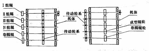
A——cantilever roll forming machine; b——closed roll forming machine
Figure 7 Schematic diagram of the roll forming machine
Figure 8 shows a schematic view of a common barrel hoop forming machine. The strip is fed from the chute 1 so that the strip position is not deflected and moved, and then the rolls of A, B, and C are rolled to form the cross-sectional shape of the desired part. When the strip comes out of the C roll, it encounters the reeling roll D; the strip is turned to the upper corner, and the guide rail 5 is guided to the coil forming.
The chute 1 is a long groove with adjustable width, which can be applied to different width strips; the handwheels 2, 3, 4 can adjust the gap between the upper and lower rollers of A, B and C to make it suitable for different thicknesses. The material can be adjusted; the hand wheel 6 can adjust the distance between the reeling roller D and the counter roller C to realize the barrel hoop molding of different diameters. The guide rail 5 can also be adjusted while the diameter of the hoop changes.

1-positioning chute; 2-A roller adjustment hand wheel; 3-B wheel adjustment hand wheel; 4-C roller adjustment hand wheel; 5-guide device; 6-D roller adjustment hand wheel
Figure 8 Schematic diagram of the barrel forming machine
Fourth, the process design points
1. Spindle diameter
As a basic starting point for the design and use of forming equipment, the diameter of the roller spindle, which is a function of the deformation force, is often considered to be a fundamental factor in strength and size. According to the relevant calculations, the diameter of the main shaft and the thickness of the plate have a relationship as shown in FIG.
The main shaft is driven by up and down constant speed drive, variable speed drive and lower shaft drive. Pay attention to the friction loss in the groove design of the roller. In order to reduce the friction between the roller and the material, a water-soluble oil mixture (2-10%) is used as the cooling lubrication.

A-sheet thickness to width ratio, width exceeds the standard case; b-sheet thickness t to width b ratio, t:b=1:20, which is the general standard case
Figure 9 Relationship between the diameter of the roll forming spindle and the thickness of the plate
2. Part shape
When considering the shape of the desired hoop, first avoid the groove that is too deep in the cross-sectional shape of the part. Select the bending radius, consider the bending properties of the material, and avoid sharp corners with too small bending radius. The formation of sharp corners is difficult to achieve the accuracy requirement i. These are the primary basic conditions.
3. Expansion of section shape
Before designing, consider the shape of the required section. Next, the drawn curved piece is gradually unfolded until it is restored to the unfolded sketch of the flat material, and then analyzed. As shown in the lower diagram of Fig. 3, the parts are reversed several times to reveal the process of gradual forming. This method is an effective research method for both simple shapes and complex sections. Further, it is possible to examine from the one roller groove type to the next roller groove type as a whole, and whether the bending process in the height direction and the width direction is unreasonable.
4. Number of rollers
The maximum height h of the strip forming is based on an upward increase in a linear relationship, that is to say a uniform transition during the forming process. The design method is to control the deformation angle of the formed straight edge to make it form at a constant speed. Experience has shown that 3 is used for general low carbon steel materials. It can be left and right, and if the extension of the edge portion is too large, the edge is prone to wrinkles. As shown in Fig. 10, the forming process of the barrel hoop of a U-shaped section is divided. If the station spacing of the rollers is taken as d in the figure, and the forming height at each station is determined, the sectional development map and the design of each roller groove type can be made.
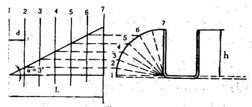
D- spacing between adjacent two sets of rollers; L-first group and last group of roller spacing; h-forming maximum height; α-forming straight edge straight rising angle (analytical geometry)
Figure 10 Number of roller sets
The determination of the number of roller sets is a difficult problem, but for the formation of a simple sectional shape, as shown in Fig. 10, it is determined that the rising angle of the formed straight side is α, the spacing of the roller station is d, and the total length of the molding apparatus is L (L is the distance between the first set of rolls and the last set of rolls), then the number n of rolls can be determined by the formula:
n=L/d=hcosα/d
5. Guide line
In order to move the sheet forward from the flat state until the desired cross-sectional shape is formed, horizontal guide lines and vertical guide lines are required. As shown in Fig. 8, the horizontal guide lines are always maintained at the same level from the first set of rollers to the last set of rollers, as a reference for determining the pitch diameter of the forming roller. The vertical guide line is perpendicular to the axis of the roller, as indicated in Figure 3, from the first set of rollers to the last set of rollers, such that the amount of forming on both sides of the guide line is an equal reference line. In a symmetrical section, this guide line is consistent with the centerline of the section.
6. The pitch diameter of the roller
The uniform diameter of the upper and lower rollers is the pitch diameter of the roller. The upper and lower roll pitch circles are separated by a horizontal guide line having a diameter which is one-half of the center-to-center distance of the upper and lower rolls, as indicated in FIG.
The molding material can be fed into the forming circle without slipping. At the roll diameter other than this point, slippage occurs between the roller and the material. It is an important issue to select the diameter of the roller pitch circle at the point of the forming roller groove type. From an ideal point of view, it is preferable to select the point at which the roller is most stressed, but these points vary on each of the constituent rollers. Here, if it is considered that the horizontal guide line passing through the third group of rollers and the diameter of the roller pitch are coincident, in each group of rollers, the diameter of the pitch circle coincides with the bottom surface of the sectional shape or the center of the sectional height. It is convenient. The length of the pitch circle is increased by about 0.5-1.0% in each set of grooves, and the material is stretched toward the last set of rolls to prevent bending and twisting.
7. Strip blank width
As in the case of mold bending, the roll formed blank width is calculated as the length of the curved neutral line, see Figure 11.
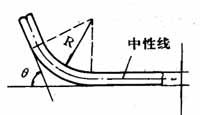
Figure 11 Length of the curved arc
In the curved part with a small radius, it must be noted that the neutral line is shifted toward the compressed side, that is, the curved inner side. If the length of the neutral line is L, the bending angle is θ, the inner bending radius is R, the thickness is t, and the distance from the inside to the neutral of the curved line is kt, then:
L = 2π(R + kt)(θ/360) =0.017458 (R ten kt)
When the neutral line is at 1/2 of the plate thickness (in the case where the bending radius is large), k = 0.5, but for a curve having a small radius, k becomes 0.4 to 0.3.
8. Roller groove type clearance
In roll forming, the thickness of the sheet does not become thick. For the curved portion, since the material is thinned, the gap can be taken to be equal to the thickness of the material. Since the displacement is in principle in addition to the diameter of the pitch circle of the roller, it is safer to obtain a point larger than the diameter of the pitch circle. Generally take 1 (1/4) of the thickness of the board. In addition, for each intermediate groove type other than the last set of roller groove types, it is preferable to make the gap larger (can be increased to 1/3 of the plate thickness. See Fig. 6.
9. Prevent rebound
The over-bending method and the method of forcibly pressurizing the groove type from the both sides of the barrel hoop in the groove of the finishing roll (the last set of forming rolls) are performed for limiting the rebound of the roll forming. Effective.
10. Prevent surface scratches
In roll forming, if the blank is placed at the radius of the shoulder of the roller (skewed), a continuous surface flaw is generated on the longitudinal surface due to the slipping action of the roller. In order to prevent such a defect, it is necessary to make the groove type wider, which is effective for forming the sheet into the inclined surface of the groove type, or by laterally pressing the side roller.
11. Roller material
Tool steel (such as T8, T10, etc.) can be used as a roller if it is quenched to a Rockwell hardness of RC60 or so. Softer materials, such as bronze and aluminum alloy rollers, can also be used to prevent surface scratches.
V. Analysis of common defects in forming barrel hoops
Scratch
Bright spots appear on some parts of the surface of the barrel hoop, sometimes accompanied by flying spurs and chips scraped off the surface of the barrel hoop during the rolling process, which destroys the surface quality of the barrel hoop and causes local shrinkage of the barrel hoop. The main reason for this is that the edge angle of the roller is too small, or the surface is not smooth after wear, or the gap is too small, or up and down, the position of the roller groove is offset.
2. Scratch
Surface scratches on the hoop may be straight and may be curved. The cause is that the surface condition of the roller is poor, or the speed is too small to be unreasonable.
3. Crack
Cracks occur at the bends. The cause is that the material is poorly plastic, the working fillet radius is too small, or the bending angle is too small.
4. stripe
The clear stripes appearing periodically on the surface of the hoop, although the hand touch has no obvious feeling, but can not be covered after painting. The reason is that the rotation resistance of the barrel hoop is too large, the speed is not uniform, and the instantaneous slip phenomenon occurs between the barrel hoop and the roller.
5. Skew
The skew phenomenon that occurs during rolling causes the width of the sides of the barrel hoop to be inconsistent, often accompanied by the distortion of the barrel hoop. The reason is that the barrel hoop is unstable and the swing is caused during the roll forming process. The reason is that each group of rollers is not adjusted on the same horizontal guide line, or the roller is swayed on the shaft.
Related links: Exploration of the forming process of the full-open steel barrel hoop (on)
Pet Toys,Cat Toys,Dog Toys,Pig Toy
Ningbo Dikai Imp&Exp Co., Ltd , http://www.longkaitoys.com